|
|
|
| J# | Description |
|---|---|
| J1 | KEYBD |
| J2 | MOUSE |
| J3 | VIDEO |
| J4 | COM2 |
| J5 | PARALLEL |
| J6 | COM1 |
| J8 | Not used |
| J9 | VESA |
| J10 | RISER SLOT |
| J11 | Auxilliary 3.3V Power |
| J12 | Primary Power |
| J13 | Not used |
| JUMPER | FUNCTION |
| J21 | JMOD |
| JUMPER | FUNCTION |
| J22 | PCI IDE |
| JUMPER | FUNCTION |
| J23 | IDE |
| JUMPER | FUNCTION |
| J24 | FLOPPY |
| J25 | SIMM BANK B |
| J26 | SIMM BANK B |
| J27 | SIMM BANK A (EMPTY) |
| J28 | SIMM BANK A (EMPTY) |
| J29 | Auxiliary 12V Fan Power |
| J30 | Auxiliary 10V Fan Power |
| J31 | RESET |
| J32 | PWR LED |
| J33 | HD LED |
| J34 | TURBO LED |
| J35 | KEYLOCK |
| J36 | EXT STANDBY |
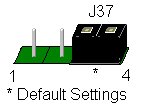
| J37 SPKR | Ext. Speaker connector |
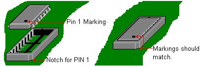
U2B1: CPU Socket
U4A1-U6B2: Level 2 Cache
AS7C256 Cache Memory 32kx8-15ns
Also see: Cache Upgrade Information
U2H1-U4J2: Main RAM
TMS444000 Main memory 4Mx1-70
Also see: RAM Memory Upgrade Information
U10A1/U11A1: Video Memory Upgrade Sockets
Also see: Video RAM Upgrade Information
U10B1/U11B1: Built-In Video Memory
MT4C16257 Video Memory 256kx16
U11D1: Cirrus Video Controller
CD-GL5434 Cirrus Logic Video Controller
SIMM Sockets
Note
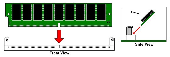
Also see: RAM Memory Upgrade Information
J1: Keyboard Port
6-Pin Mini-DIN Keyboard Connector

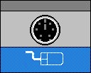
J2: Mouse Port
6-Pin Mini-DIN Mouse Connector
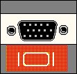
J3: Video Port
15-Pin HD Sub-D Video Connector
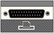
J5: Parallel Port
25-Pin D Shell Parallel Port Connector
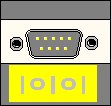
J6: Serial Port
9-Pin D-Shell Serial Port Connector
J9: VESA
26-Pin (2 x 13 Header) Video Feature Connector
J10: Riser
Riser Card Connector
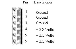
J11: 3.3V PCI Power Connector
PCI Bus Power Connector
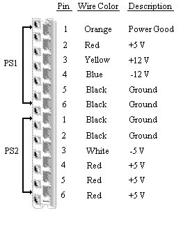
J12: Main Power Connector
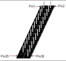
J21: Modem
20-Pin (2 x 10 Header) DB Modem Connector
J22: PCI IDE Connector
40-Pin (2 x 20 Header) PCI Hard Drive Connector
J23: ISA IDE Connector
40-Pin (2 x 20 Header) ISA Hard Drive Connector
J24: Floppy Connector
34-Pin (2 x 17 Header) Floppy Drive Connector
J29: Auxiliary 12-Volt Fan Power Connector
Pin 1 Ground
Pin 2 +12 Volts
Pin 3 Ground
J30: Auxiliary 10-Volt Fan Power Connector
Pin 1 Ground
Pin 2 +10 Volts
Pin 3 Ground